
Planning an Ionizing Bar Retrofit: A Pre-Installation Checklist
Before ordering an ionizing bar for an existing line, prepare a drawing that shows what the bar must treat and what surrounds it. A useful retrofit brief connects the material path, mounting space, connections and planned measurements, so each unresolved detail has someone responsible for checking it.
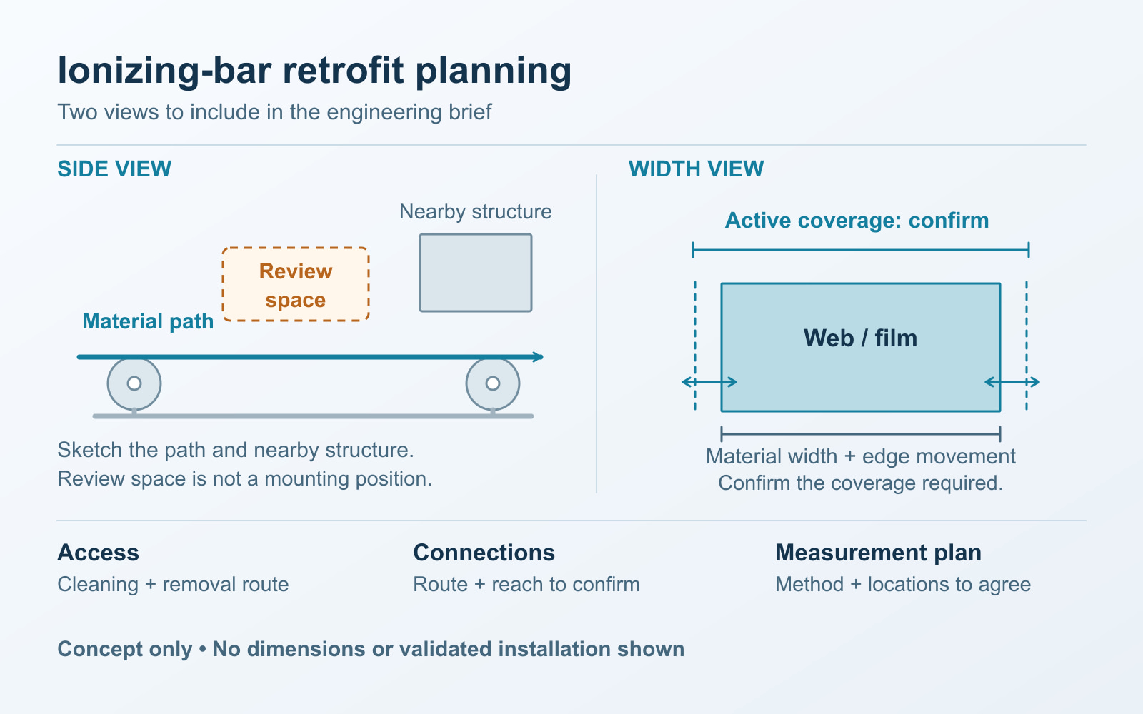
Original conceptual planning diagram. The dashed space is a review area, not a specified mounting position. Confirm active coverage against the material width and edge movement. No dimensions or validated installation are shown.
Start with the existing line and a defined problem
Use this proposed planning worksheet to prepare an engineering review. It does not prescribe installation distances or replace equipment instructions. Begin with the process step that needs attention: which material, which face and which observed problem? Name the person who will decide whether a later trial meets the process requirement.
The ESD Association's principles of control distinguish grounding conductive items from neutralizing charge on insulators, and recommend understanding materials and processes before choosing controls. On the drawing, identify the insulating web separately from conductive machine parts. Adding ionization does not replace a review of the applicable grounding arrangements.
Give the sketch a machine ID, revision and fixed reference points. Mark travel direction, roller contacts and separations, nearby structure and the downstream operation of concern. Label candidate positions on that same drawing. Our ionizing-bar guide explains the basic equipment function; this brief addresses how to assess a proposed addition to an existing machine.
Show the material faces, width and movement
Label the two faces consistently, including coatings, liners or exposed surfaces. If the web turns between operations, carry those face labels through the sketch. A photograph marked “top side” can become ambiguous after a change in path.
Record the material widths and expected edge movement for the intended jobs. Identify whether the proposed position changes during threading, a roll change or another operating configuration. Where the movement range is unknown, request an observation or drawing instead of assuming the web remains centered.
| Drawing item | What to confirm |
|---|---|
| Bar body | Overall dimensions and occupied space, including connectors. |
| Active span | The documented emitter span and the coverage question for this application. |
| Mounting pattern | Attachment locations and the proposed support arrangement. |
| Material envelope | Material width and the positions its faces and edges can occupy. |
These are separate drawing items. An overall bar length does not establish active coverage, and a suitable active span does not establish mechanical fit. Request the current drawing for the proposed model and length.
Review support, clearance and access together
For each candidate, record the proposed bar-to-material gap separately from space needed around the body, connector and bracket. Ask machine engineering to review the support and the range of material positions. Leave required clearances to the applicable equipment documentation and installation review; this worksheet provides no universal distance.
Show the normal guarded configuration. Can the planned installation, inspection and servicing be carried out using approved access? Record how a technician would reach the bar for the manufacturer's maintenance procedure and how the assembly could be removed. A location that looks accessible in an open-machine photograph still needs review with the production arrangement shown.
Mark cable routes and nearby moving parts on the drawing. Record access questions for the responsible engineer; do not resolve a planning gap by bypassing a guard or improvising a reach into operating equipment.
Confirm connections before specifying integration
List what the line can provide and what the selected equipment requires: electrical supply, mating connector, cable route and any intended control or alarm connection. Ask for the relevant connector and interface documentation. A connector shape or a port shown in a photograph does not identify its pinout, signal type or communication protocol.
Give controls engineering a practical question to answer: is the proposal a standalone installation, or must the line receive a status signal or control a function? If integration is intended, record the requested behavior and obtain confirmation that the chosen configuration supports it. Keep unresolved functions out of the purchase specification until confirmed.
For a model under consideration, use its current documentation, such as the ST-G product information, as the starting point for clarification. This planning brief contains no wiring instructions.
Agree what will be measured and who accepts it
The public scope of IEC 61340-4-7:2025 distinguishes ionizer performance measurements under specified conditions from qualification for a user's application. A catalogue figure therefore needs its conditions understood before it is used in the retrofit decision. Our ionizer datasheet comparison guide covers that review.
Keep three questions separate: how the ionizer will be checked, what will be measured on the material, and what production outcome matters. The ESD Association's instrumentation guidance explains that instrument choice depends on the measurement and distinguishes field indications from ionizer balance and decay-time measurements.
On the drawing, reserve proposed test points and identify the intended instrument, method and operating state. Record measurement geometry separately from the bar's installation gap. The process and quality teams should agree acceptance criteria, access and responsibilities before the trial. For an existing charge problem, use the separate static-return investigation to organize diagnostic observations.
Turn unknowns into an evidence request
Adapt this proposed worksheet to the project. Replace the example issue with the exact question, attach the drawing reference and assign a named reviewer. Add the answer and decision date when evidence arrives; a blank is not an approval.
| Unresolved issue | Evidence to request | Suggested owner |
|---|---|---|
| Material width or edge range unclear | Marked drawing or operating observation | Process owner |
| Active span or mounting pattern unconfirmed | Current product drawing | Equipment supplier |
| Support or guarded access unresolved | Machine layout and access review | Machine engineering |
| Connection or alarm behavior unknown | Interface documentation | Controls engineering |
| Test location or criterion undecided | Agreed measurement and acceptance plan | Process and quality teams |
Blank handover record
| Project information | Record or document reference |
|---|---|
| Machine ID, drawing revision and candidate position | ______ |
| Material, target face, width and movement range | ______ |
| Product drawing, support and access review | ______ |
| Supply, connector and intended interfaces | ______ |
| Measurement plan, criterion and named acceptance owner | ______ |
| Open issue, requested evidence, reviewer and decision date | ______ |
If two candidate locations remain, give each its own open questions. Choose the next drawing, clarification or approved test that can resolve the difference, rather than treating convenient mounting space as proof of suitability.
Frequently asked questions
What information is needed before choosing an ionizing bar length?
Provide the material width, expected edge movement, target face and available mounting space. Ask for a drawing that distinguishes overall body length, active emitter span and mounting pattern. A matching overall length does not establish coverage or physical fit on the line.
Can an ionizing bar go in the nearest available space?
Treat that space as a candidate for review. Record the web path, nearby structure, normal guarded configuration, connection route and service access. The equipment and process teams need to confirm the installation and qualification plan before accepting the position.
Does a catalogue decay time prove that a retrofit will work?
No. A decay-time figure describes a test under particular conditions. It does not, by itself, establish the result on your moving material. Confirm the test conditions, then agree application-specific measurements and acceptance criteria with the process owner.
Prepare your ionizing-bar retrofit brief
Send an annotated line drawing, material details, width and movement range, candidate positions and connection questions. Include the process requirement and planned measurements so our team can discuss the information needed for equipment selection.