
Comparing Ionizer Datasheets: Which Test Conditions Must Match?
A decay-time number describes a defined voltage change on a defined test target. Before comparing two ionizers, check the conditions behind the numbers, then plan a separate verification on your material.
Start by separating decay time from ion balance
Compare the test method, target and operating conditions before ranking ionizer specifications. Decay time and ion balance answer different questions. The public ESDA summary of ANSI/ESD STM3.1-2024 identifies discharge time and offset voltage as separate measurements made under specified conditions.
| Reported value | What to establish | What it does not establish |
|---|---|---|
| Decay or discharge time | The time for a test target to move between stated voltage endpoints, for a stated polarity. | A production line speed or a result over every working distance. |
| Ion balance or offset voltage | The voltage observed on the test plate in the ionized environment, using the reported measurement method. | The residual voltage on any film, PCB or insulating part passing through the equipment. |
| Emitter output voltage | The electrical quantity, waveform definition and measurement reference behind the kV figure. | A ranking of neutralization performance based on kV alone. |
For a first comparison, give each result its own row. Do not combine the fastest decay figure, the best offset and the largest working distance into one operating claim unless the report demonstrates that combination.
Read the voltage endpoints and both polarities
A time without a start and stop voltage is an incomplete comparison. KEYENCE's official technical Q&A gives examples using ±1000 V to ±100 V and identifies the charged-plate test setup and air conditions. In that notation, the two tests are +1000 V to +100 V and −1000 V to −100 V. It does not mean a sweep from a positive voltage to a negative one.
Record the positive and negative results separately. If a sheet gives one headline time, ask whether it is a typical result, a maximum, an average or one polarity only. A result over a different voltage interval cannot simply be rescaled into the interval you need.
A useful comparison question: “Can you supply both polarity results for the same voltage endpoints and the measurement positions shown in our proposed installation?” Keep any unavailable answer marked as not reported.
Compare the test target and its position
A charged plate monitor, or CPM, provides a controlled conductive target. Its plate is not the same object as a moving film or assembled product. Simco-Ion's CPM Measurements application note explains why plate area, capacitance, surrounding objects and instrument response matter to the readings.
Ask how distance was measured: from which part of the ionizer to which part of the target, and at what orientation? Keep a sketch or test-point map with the results. A centre reading is not an edge reading, and a near-field result is not evidence for the same performance farther away.
Also check how offset was recorded. An average, a range and positive/negative peaks are different descriptions, especially for a changing signal. The same Simco-Ion note distinguishes these readings; preserve the original description and observation period instead of reducing every result to an unexplained “±” number.
Record airflow and settings without forcing unlike equipment to be identical
“Same conditions” needs a practical definition. Agree on the application target, measurement geometry and evaluation method. Then document the configuration each candidate actually requires. Different designs may need different operating modes or air arrangements; hiding those differences makes a comparison less useful.
The Simco-Ion Ioncell manual, Rev E illustrates this point by reporting conditions for configurations with and without a fan and for an air-tube arrangement. The tables identify distance and, where applicable, air-supply details. Those model-specific settings are not recommendations for another ionizer.
For your review, record the fan setting, air pressure and flow where available, tubing or nozzle arrangement, background airflow and the selected control settings. Pressure and flow need separate fields. If a supplier changes settings between offset and decay measurements, keep that change visible rather than treating the results as one tested configuration.
A blank ionizer datasheet comparison worksheet
Copy this table into the enquiry or trial record. Fill each column from the relevant report, with its units and source page. Use “not reported” for missing information; use “not applicable” only when the field genuinely does not apply to that configuration.
| Record this field | Candidate A | Candidate B |
|---|---|---|
| Model, configuration and document revision | ________ | ________ |
| Test method and edition; report date | ________ | ________ |
| CPM model, plate size and capacitance | ________ | ________ |
| Distance reference, orientation and test-point map | ________ | ________ |
| Positive decay: start voltage, stop voltage, time | ________ | ________ |
| Negative decay: start voltage, stop voltage, time | ________ | ________ |
| Offset: average, peaks or range; observation period | ________ | ________ |
| Operating mode, frequency and control settings | ________ | ________ |
| Fan setting or air supply; pressure and flow if reported | ________ | ________ |
| Background airflow, temperature and humidity | ________ | ________ |
| Emitter condition; test preparation and repetitions | ________ | ________ |
| Missing information and supplier response | ________ | ________ |
Attach the test-point sketch and retain separate results for each point. For a longer bar or a wider work area, ask which positions were actually tested. Do not fill the gaps by assuming that one centre-point result covers the whole area.
Use the comparison to plan the application check
Comparable datasheets help narrow a shortlist; they do not finish the production trial. SMC's IZT44/45 catalogue identifies its charged-plate conditions and cautions that results on the actual object depend on its material and dimensions. Its stated test-method edition should also stay attached to those figures rather than being silently replaced by a newer edition.
Define the actual task
Record the material, exposed surfaces, movement or handling sequence, available space and the process requirement. Identify where charge is observed and where the result needs to be checked.
Agree what will be measured
Keep the CPM comparison separate from measurements on the actual material. Define the instrument method, measurement location and geometry for each. Set acceptance criteria with the process owner; do not adopt a supplier's ion-balance figure as a universal material-residual limit.
Review gaps before selecting a configuration
Sort the comparison into documented conditions, unresolved conditions and application checks still needed. If one candidate has a shorter headline time at a different distance, the immediate outcome is a request for comparable evidence, not a declaration that it is the faster choice for the line.
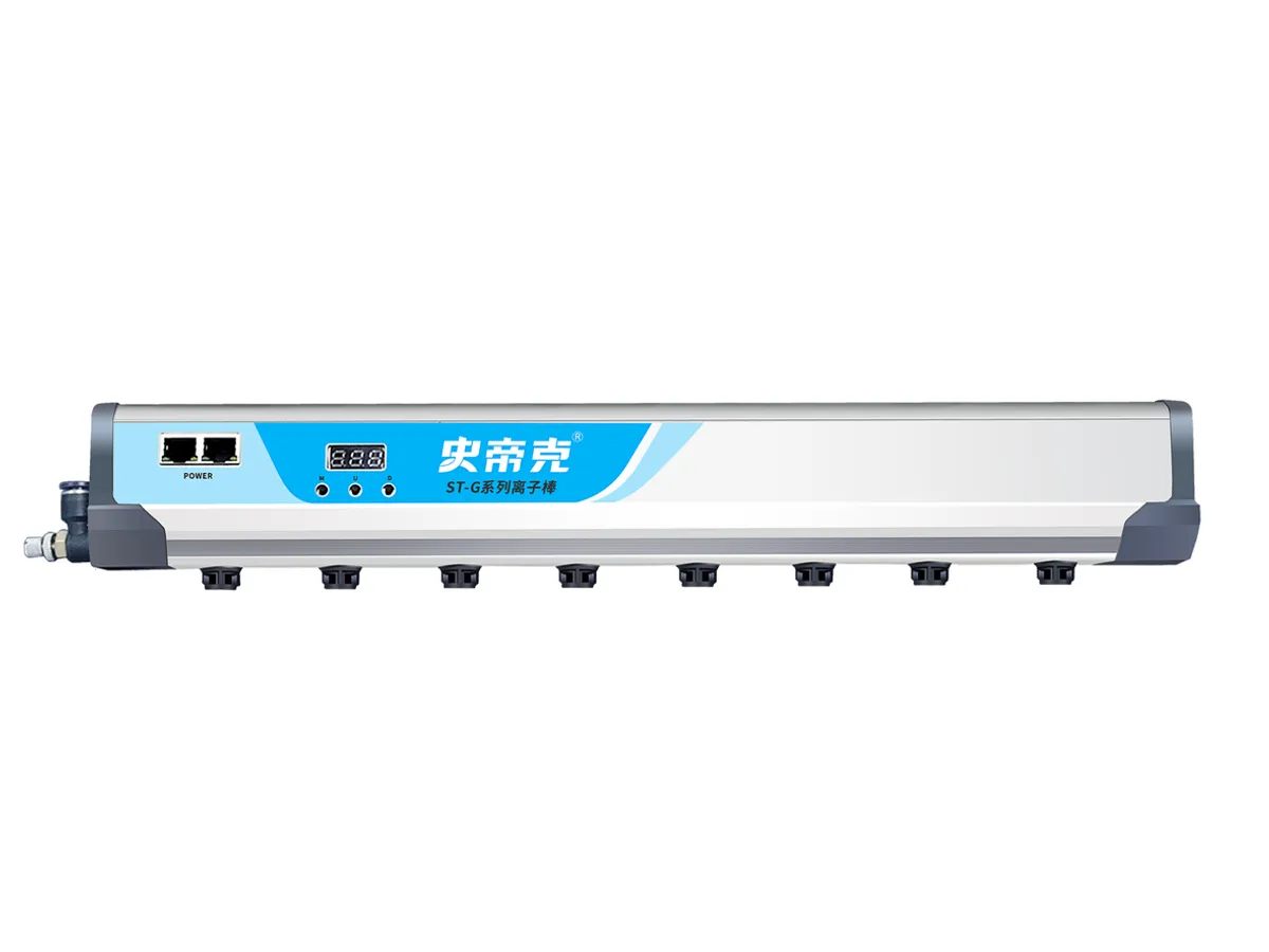
For related product context, our ionizing air blower comparison keeps reported conditions alongside model data. The installation planning section separates a test-plate check from a check on the actual part. For a bar application, review the ST-G product information together with the conditions needed for your installation.
Frequently asked questions
Can I compare two ionizers using decay time alone?
Only after checking what each time measures: starting and ending voltage, polarity, test target, measurement position and operating conditions. A shorter time from a different setup does not establish better performance for your application. Review offset voltage separately and verify the selected configuration on the actual process.
Is ion balance the residual voltage on my film or PCB?
No. A charged-plate ion-balance or offset-voltage result describes the test plate under the reported conditions. It cannot be substituted for a measurement on your material. The application needs its own measurement position, instrument method and acceptance criterion.
What should I request when a datasheet omits test conditions?
Request the report and revision behind the rating, both polarity results, the voltage endpoints, instrument and plate details, measurement geometry and operating settings. Mark missing fields as not reported. Do not infer a whole working-area result from a centre-point measurement or a universal operating speed from a static decay-time figure.
Need help comparing ionizer configurations?
Send the available datasheets, a layout sketch and your process requirement. Our team can review the documented conditions, identify missing information and discuss a suitable application trial.