The ST-G Ionizing Bar: How to Specify, Mount and Verify an Anti Static Bar
Most anti static bars fail on a line for one of three reasons: the bar is mounted where the charge isn't, the ion balance is too loose for the material, or nobody ever measured whether it worked. None of those are catalogue problems. This is what the ST-G actually does, and the four decisions you have to get right when you fit one.
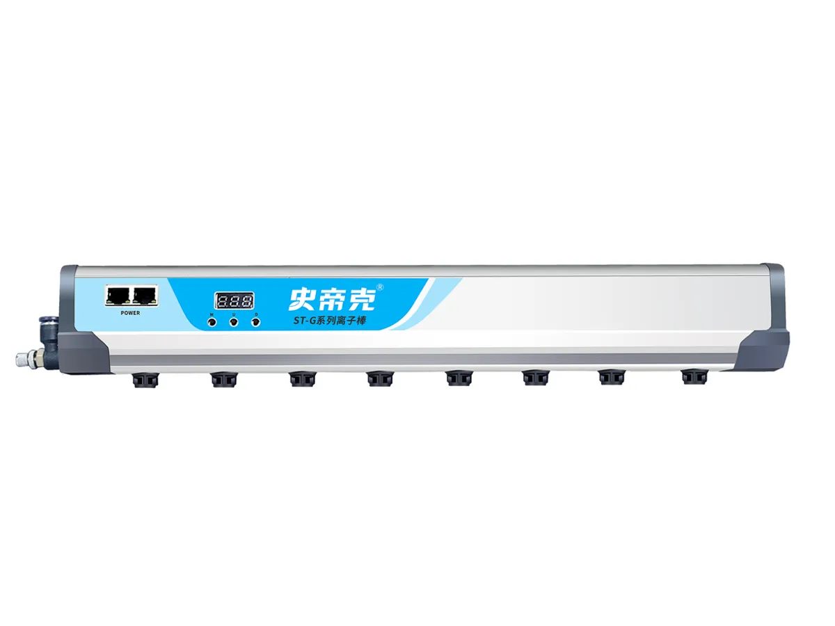
The charge is created where material separates
Static on a production line is not ambient. It is generated at a specific point, at the moment two surfaces separate: film peeling off a roller, a sheet lifting off a stack, a moulded part releasing from a tool, a panel coming off a belt. That separation is where the bar belongs.
This is the single most common installation mistake. A bar mounted after a cleaning station, downstream of the separation point, is neutralizing a surface that will simply recharge at the next roller. The material arrives at the customer's inspection step charged again, and the conclusion is that the bar does not work. Put the bar at the separation point, and if the web separates at several points, expect to need more than one.
Ion balance is the number that decides whether it holds
An ionizing bar produces positive and negative ions by corona discharge, and the charged surface pulls whichever polarity it needs until it reaches neutral. The process is self-limiting — once the surface is neutral, ion uptake stops.
The mechanism is covered in more depth in what is an ionizing bar. What matters here is how close to zero the bar can actually hold that surface. That is the ion balance figure, and it is where the three Shidike bar series differ:
| Series | Ion balance | Method | Specified when |
|---|---|---|---|
| ST-G | ±50 V | Pulsed AC, single emitter pin | The default. Tightest balance in the range. |
| ST-E | ±80 V | High-frequency pulsed DC, alternating fixed-polarity pins | Wide or long spans, where ordinary bars drift at the edges. |
| ST-F | ±100 V | Pulsed DC, Hibweer L.C.C. | High line speed — neutralizes 2.5× faster. |
The ST-G reaches ±50 V by applying alternating positive and negative high voltage to a single emitter pin, rather than splitting the job across pins of fixed polarity. One pin producing both polarities means both ion clouds originate at the same point, which is what removes the striping — the alternating over- and under-neutralized bands along the web that conventional AC bars are known for. Pulse frequency is adjustable, so the same bar suits a web moving at speed and a stationary workspace.
Under 100 V is the practical threshold for PCB, FPC, SMT, polarizer and optical film work. Above it, residual charge is still strong enough to pull particles back out of the air onto a surface you have just cleaned — which is why a cleaning machine without static control solves about half the problem.
The high voltage is generated inside the bar
A conventional ionizing bar is fed from a separate high-voltage power supply box, connected by a shielded high-voltage cable. That box needs panel space, and the cable has a fixed length and a bend radius, which together decide where the bar can physically go.
The ST-G takes a DC 24 V supply and generates its 6.5 kV DC pulse internally, drawing 12 W. There is no external supply box and no high-voltage cable to route, so the bar mounts where the process needs it rather than where the cable reaches. On a retrofit into a machine that is already running, this is usually the difference between a straightforward installation and a rebuild.
The full explanation of what that figure means, and why it is the wrong number to compare bars on, is in ionizing bar voltage output. It also self-monitors: abnormal discharge raises an alarm and cuts the high voltage automatically, so a contaminated or damaged bar announces itself instead of silently under-performing.
Specifications
| Input voltage | DC 24 V | Power | 12 W |
|---|---|---|---|
| Output | 6.5 kV DC pulse (pulsed AC) | Ion generation | Corona discharge |
| Ion balance | ±50 V | Static decay time | 1 s |
| Working distance | 30–1000 mm | Bar length | 300 mm – 3 m, made to order |
| Cross-section | 30 × 82 mm | Compressed air | Not required |
| Temperature | 0–45 °C, no condensation | Humidity | 15–75 % RH |
Working out the mounting pitch
Because bars are cut to length, the mounting holes are not at a fixed catalogue spacing — but they are predictable. The distance between the two mounting points is:
P = L − 120 mm
where L is the ordered bar length and P is the mounting pitch. A 1500 mm bar mounts on 1380 mm centres; a 2400 mm bar on 2280 mm centres. You can drill the machine frame from the order confirmation, before the bar arrives, which takes the installation off the critical path.
Size the bar to the full charged width of the material, not the middle of it. Charge does not stop at the edge of the useful area, and an undersized bar leaves charged margins that will still attract contamination.
Verify it, do not assume it
A running bar and a working bar are not the same thing. Emitter pins collect contamination, mounting gets moved during maintenance, and line speed changes after commissioning. None of that shows on the front panel.
Take a surface voltage reading with a static field meter, at the real line speed with the real material, at two points: immediately before the bar and immediately after it. Record both. That before-and-after pair is the only evidence that the installation is doing its job, and it is what turns a static problem from an argument into a number. Re-check it whenever the material, the speed or the mounting changes.
Common questions
What ion balance does an anti static bar need?
It depends on what the material is worth. For general packaging, plastics and textile work, a few hundred volts of residual offset is harmless. For PCB, FPC, SMT and optical film work the target is under 100 V, because that is the range where residual charge stops attracting particles back onto a surface you have just cleaned. The ST-G holds ±50 V, the tightest of the three Shidike bar series.
How far from the material should the bar be mounted?
Anywhere from 30 mm to 1000 mm. Closer is faster, so mount as close as the mechanics and the safety clearance allow. The 1 m upper limit is what lets a single bar cover a gantry or an overhead position where a closer mount is impossible.
Does the ST-G need compressed air?
No. Within the 1 m working range the ions reach the surface without assistance. Air assistance is only specified when the target sits beyond that range.
What length of bar should I order?
The bar should cover the full charged width of the material, not just the middle of it. Bars are made to order from 300 mm to 3 m, so give us the material width and we cut to it.
How do I know the bar is actually working?
Measure. Take a surface voltage reading with a static field meter before the bar and after it, at the real line speed with the real material. A bar that has drifted, is mounted too far away, or has contaminated emitter pins will still look like it is running. The only proof is the reading.
Send us the application
Give us the material, the charged width, the line speed, the mounting space and either a measured surface voltage or the defect you are seeing. We will come back with a series, a bar length, a mounting position and a unit count.